
Original price was: $565.00.$98.99Current price is: $98.99.
- Experience Quality, Shop with Us
- Quality that lasts, prices that don't.
- Where quality meets convenience.
- Get Quality, Get More

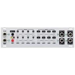
The Doepfer A-157 Trigger Sequencer Subsystem is a trigger sequencer subsystem that generates eight trigger signals controlled by a 8×16 LED/button matrix (some customers call it “Miniature Schaltwerk” as it is based on the same matrix as the no longer available Schaltwerk). The subsystem contains three modules:
- A-157-1: 8 x 16 LED/button matrix and function addressing buttons/LEDs
- A-157-2: Trigger Output module
- A-157-3: Control Inputs module
The LED/button matrix module A-157-1 is the core of the subsystem. It is used to set or reset the trigger event on each of the 16 steps of each of the 8 rows. In addition the buttons and LEDs of the matrix are used for other functions too (like setting the first and last step of each row or addressing the preset memory).
The Trigger Output module A-157-2 outputs the 8 trigger signals and has an LED display for each trigger available.
The Control Inputs module A-157-3 has manual controls and trigger inputs available for the basic control functions start, stop, reset and clock. In addition four functions inputs are available which will be used in future firmware versions to assign these inputs to special functions (e.g. shifting a row left or right by means of an external gate/trigger signal or a second set of start, stop, reset and clock for individual rows).
The three modules are internally connected via ribbon cables and can be arranged also in another layout (e.g. A-157-2/3 on the right side of the A-157-1 or in a row above or below). The modules are available only as a complete set.
A-157-1
In addition to the main 8×16 matrix this modules contains also the buttons and LEDs for these functions:
- Mute button for each row, these buttons are planned also as submenu buttons for future firmware version
- Select button for each row, used to address one or more rows for subsequent functions (e.g. first step, last step, shift left, shift right …)
- Function buttons/LEDs, the functions are divided into two levels, the second level is invoked by the SHIFT button/LED on the buttom right position
- The functions without SHIFT are printed black, the SHIFT-functions are printed in reverse
- On the front plate there are already printed some texts for future/additional features/functions. Mainly in the SHIFT-plane
A-157-2
This is the trigger/gate output module that has 8 sockets with assigned LEDs available. The width of the output signal depends upon the width of the incoming clock signal, i.e. the width of the output signals is the same as the width of the incoming clock signal.
The level of the output signal is software controlled (i.e. not fixed to a certain value) as each outputs is equipped with a separate DAC (digital-to-analog converter). In the first version of the firmware the level is fixed to ?V.
A-157-3
| Condition | New |
|---|---|
| Depth | 45, mm |
| Chassis | Module |
| Module Type | Eurorack |
| Module Slot Count | 52hp |
| Connector Type | 3.5, mm |
Be the first to review “Cheapest ???? Doepfer A-157 Trigger Sequencer Subsystem ????”
Related products
Modular Synth Sequencing
Modular Synth Sequencing

Modular Synth Sequencing
Modular Synth Sequencing
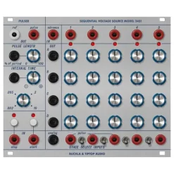
Deals ???? Tiptop Audio Buchla Model 245t Sequential Voltage Source Module ????
Modular Synth Sequencing
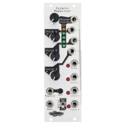
Cheap ???? Noise Engineering Zularic Repetitor – Silver ????
Modular Synth Sequencing
Modular Synth Sequencing
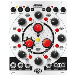
Coupon ???? Xaoc Devices Moskwa II Eight-Step Sequencer Eurorack Module ????
Modular Synth Sequencing
Reviews
There are no reviews yet.